Overview
In this project, I explored and implemented various types of geometric modeling strategies, starting with basic Bezier Curves and surfaces, then looking at the implementation of Phong shading on a mesh, before making use of the Half-Edge data structure to perform many types of operations on meshes, including edge flipping, edge splitting, and mesh upsampling. This project was a very fun and interactive way to get me exposed to these different techniques, and it was very satisfying to see my implementations visualized in a 3D form. It was also impressive how the Half-Edge data structure really allows for the easy traversal through a very complicated mesh, and how everything works almost magically together to create beautiful models.
Section I: Bezier Curves and Surfaces
Part 1: Bezier curves with 1D de Casteljau subdivision
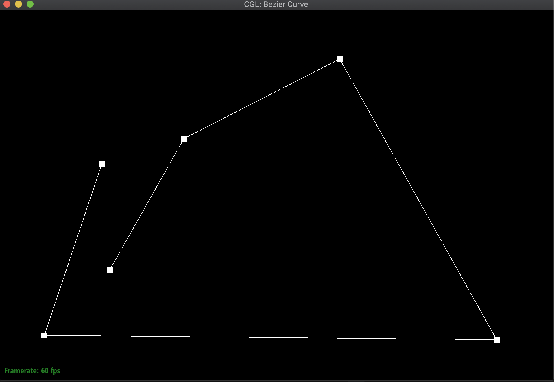
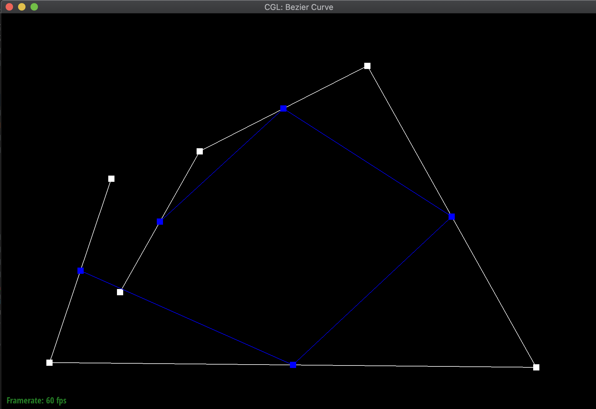
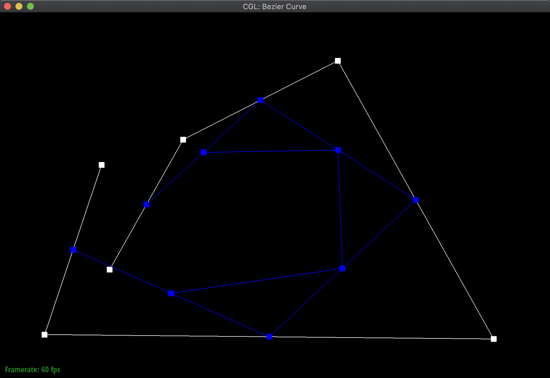
The general idea behind De Casteljau's Algorithm is that given a set of n control points, we can linearly interpolate them in pairs, and select a new control point on each line created at some offset t away from the original control point. This will create a new set of n - 1 control points. We can continue to do this until we have exactly one control point, which will lie on the Bezier curve specified by our original set of control points. Therefore, we can do this for many values of t in order to sketch out the full curve through the interpolation of those points.
To implement this in code, I defined a function evaluate_step where given a set of control points, it linearly interpolates a point with its adjacent point, and then finds the position along that line at offset t using the following equation:
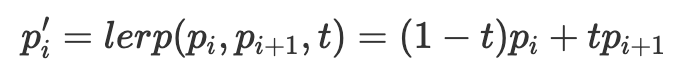
The function then returns a new vector with each new lerp'd control point of length n - 1. This function can then be called multiple times to construct a Bezier curve given a set of control points.
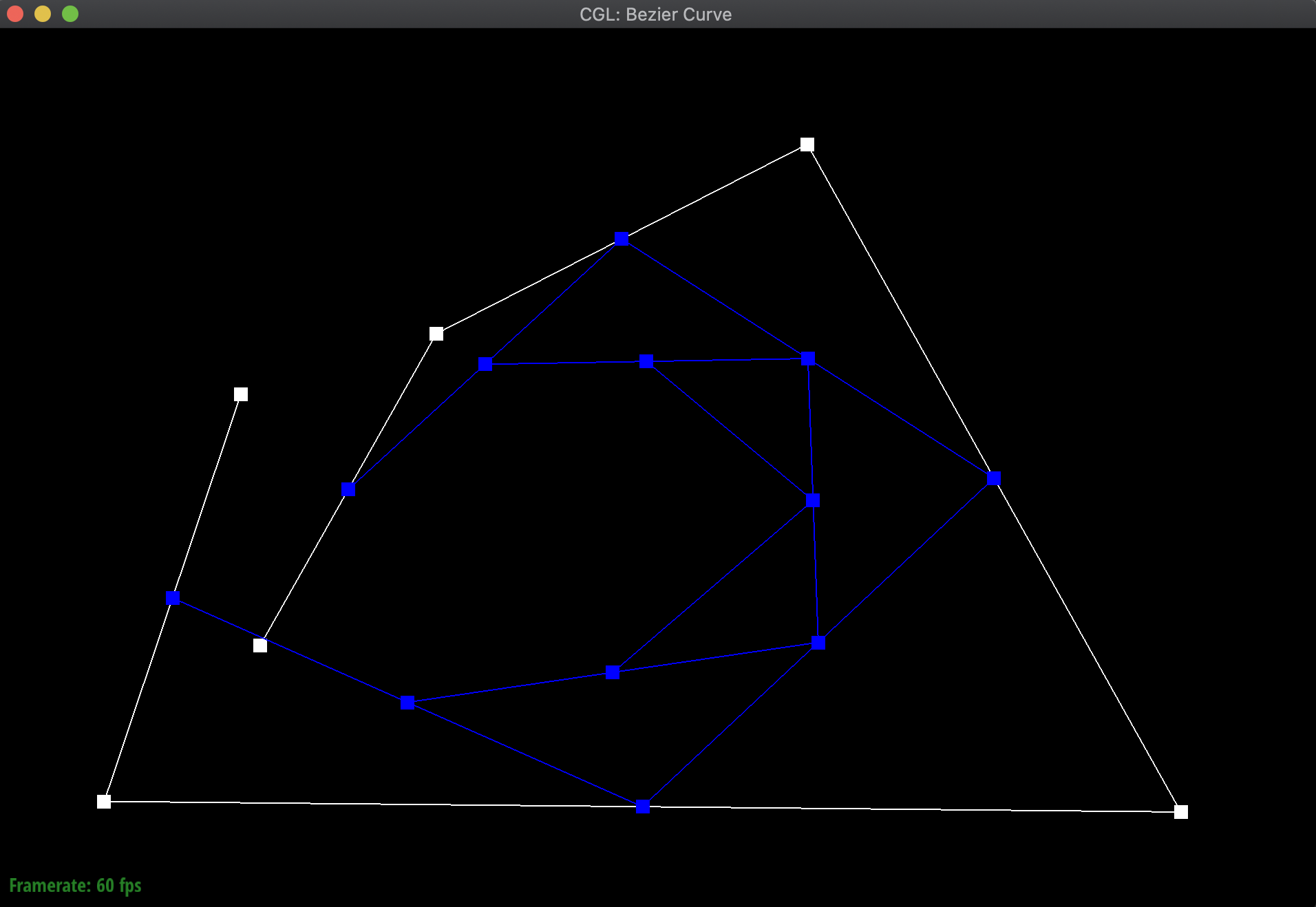
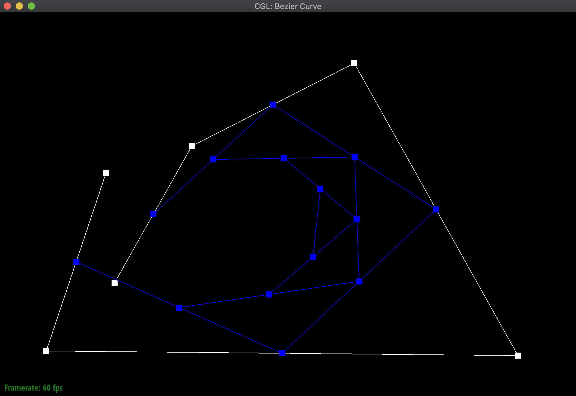
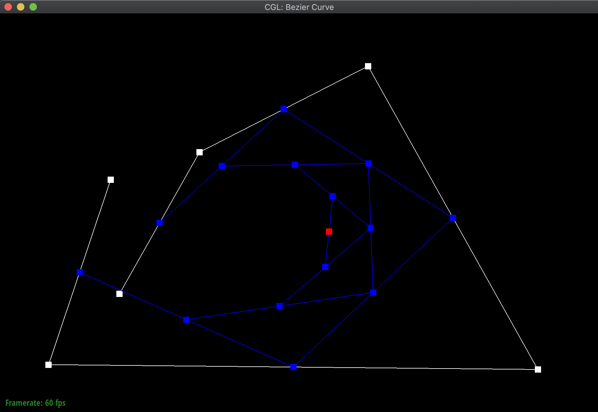
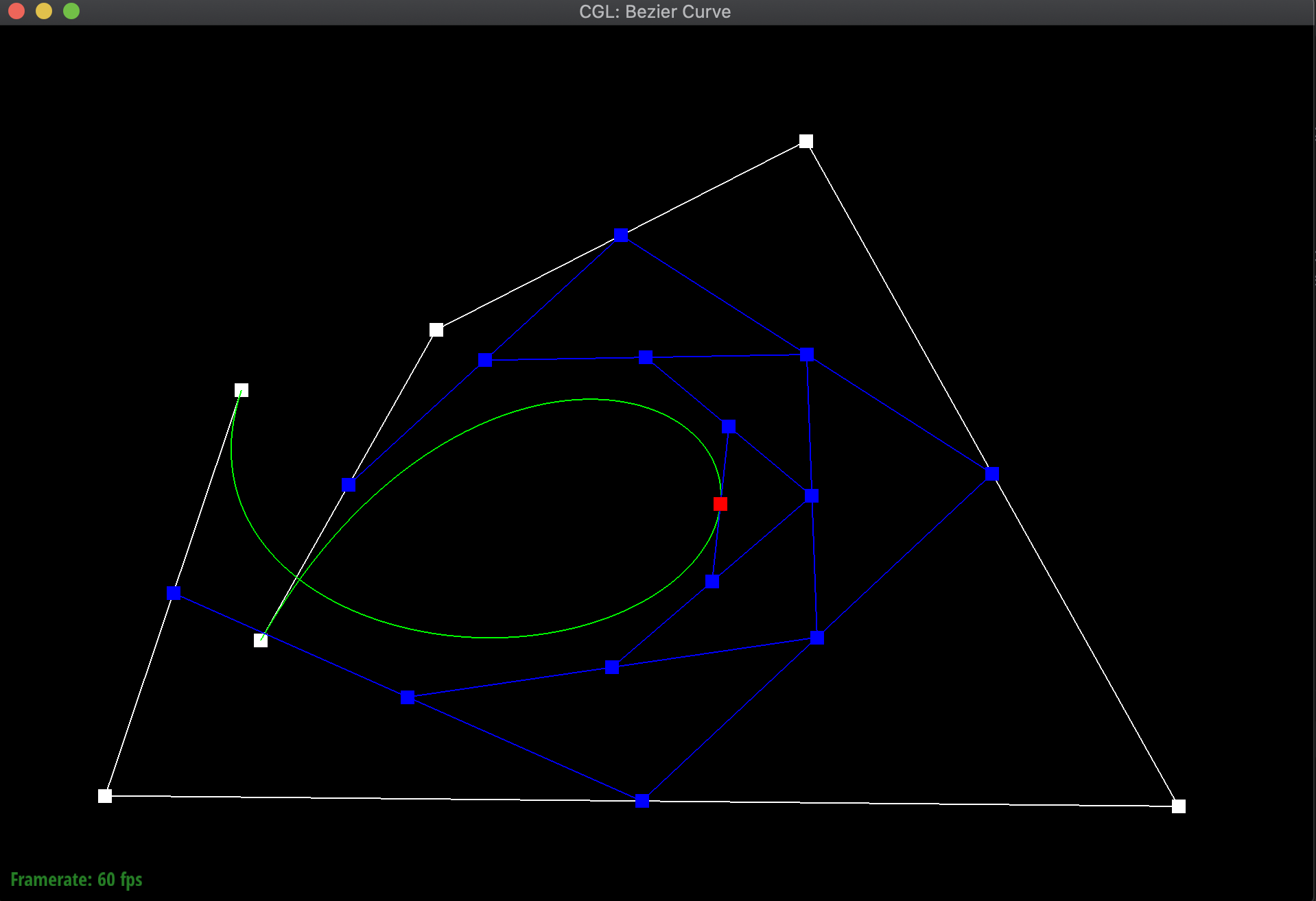
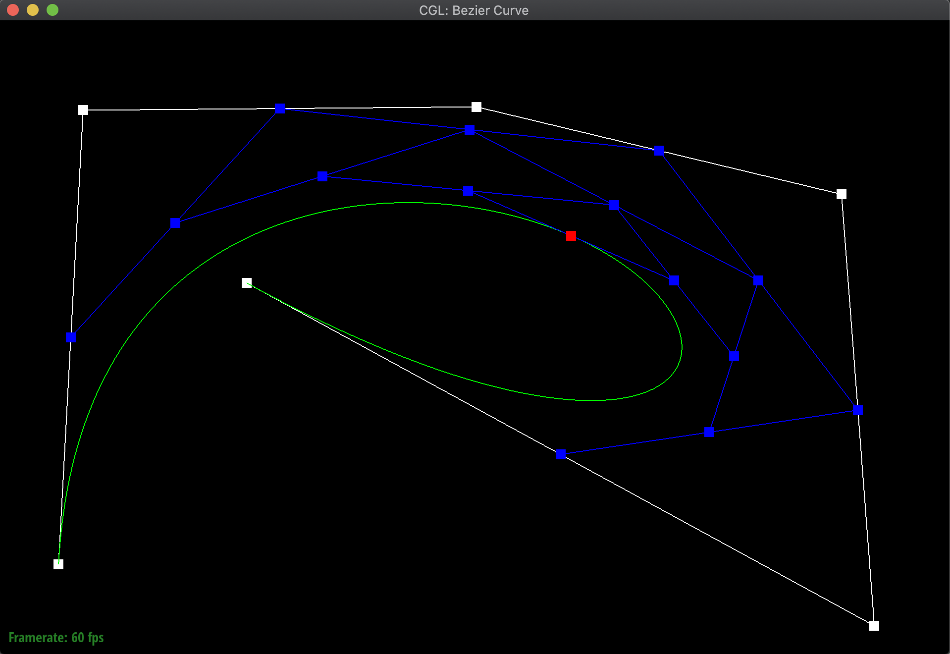
To illustrate my code at work, I created a new Bezier curve (.bzc) file with 6 control points. Below are the results of evaluating my function over and over again to eventually find a particular point on the curve for a given t, along with the final resulting Bezier curve:
|
|
|
|
|
|
|
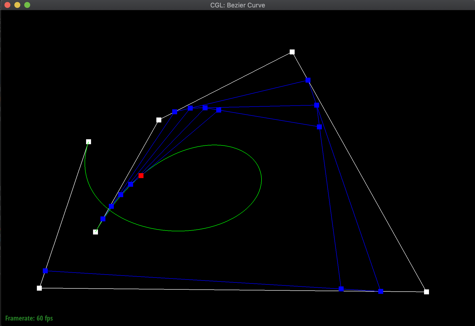
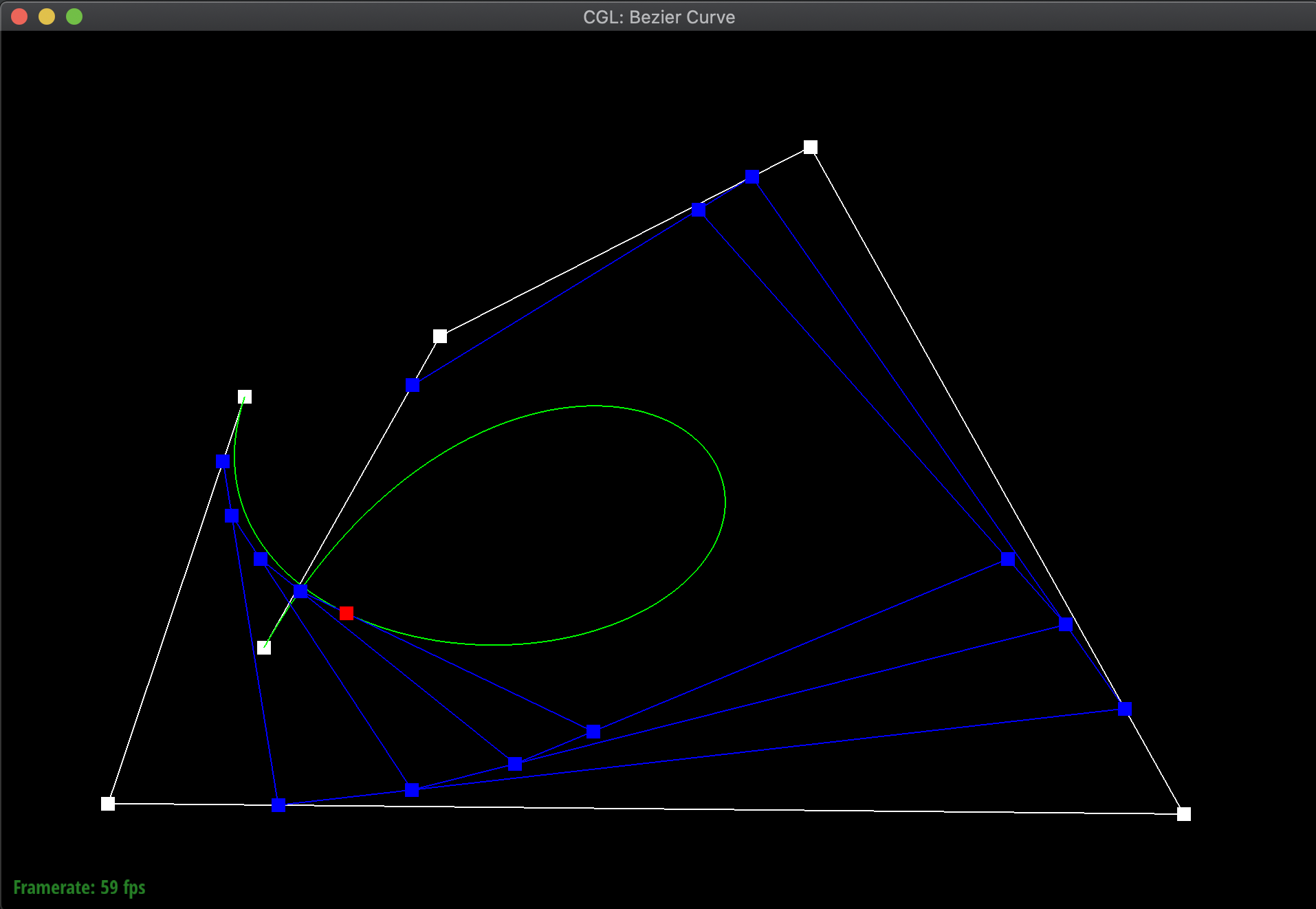
Additionally, here are additional pictures of the same Bezier curve, first after shifting around the original control points, then adjusting the t value around both smaller and bigger. Notice how even when shifting around the t value, the point still remains on the curve:
|
|
|
Part 2: Bezier surfaces with separable 1D de Casteljau subdivision
We can now extend this concept of Bezier curves into an evaluation of Bezier surfaces. For example, if we want to evaluate some surface position corresponding to parameters (u,v), given an m x n set of control points, what we can do is first use De Casteljau's Algorithm on every row of the set of control points, to find each point on that row's Bezier curve that corresponds to offset u. Then, using those points, we can use De Casteljau's Algorithm again with offset v to find a point on the Bezier surface. Using this method, we can actually form surfaces in 3D space!
In order to implement this, I modified evaluate_step and generalized it to a 3D Vector, since the points I was working with were now in 3D space. I then defined a function evaluate_1D that iteratively called evaluate_step on a given offset until the remaining vector had only one point, which would be the returned point on the Bezier curve. Lastly, I defined an evaluate function that first iterated through the rows of the given control_points and called evaluate_1D on each of them with an offset of u in order to get a vector of points again. Then, I took those points, and evaluated the point on the Bezier curve formed by them at the offset v in order to get the corresponding point on the Bezier surface.
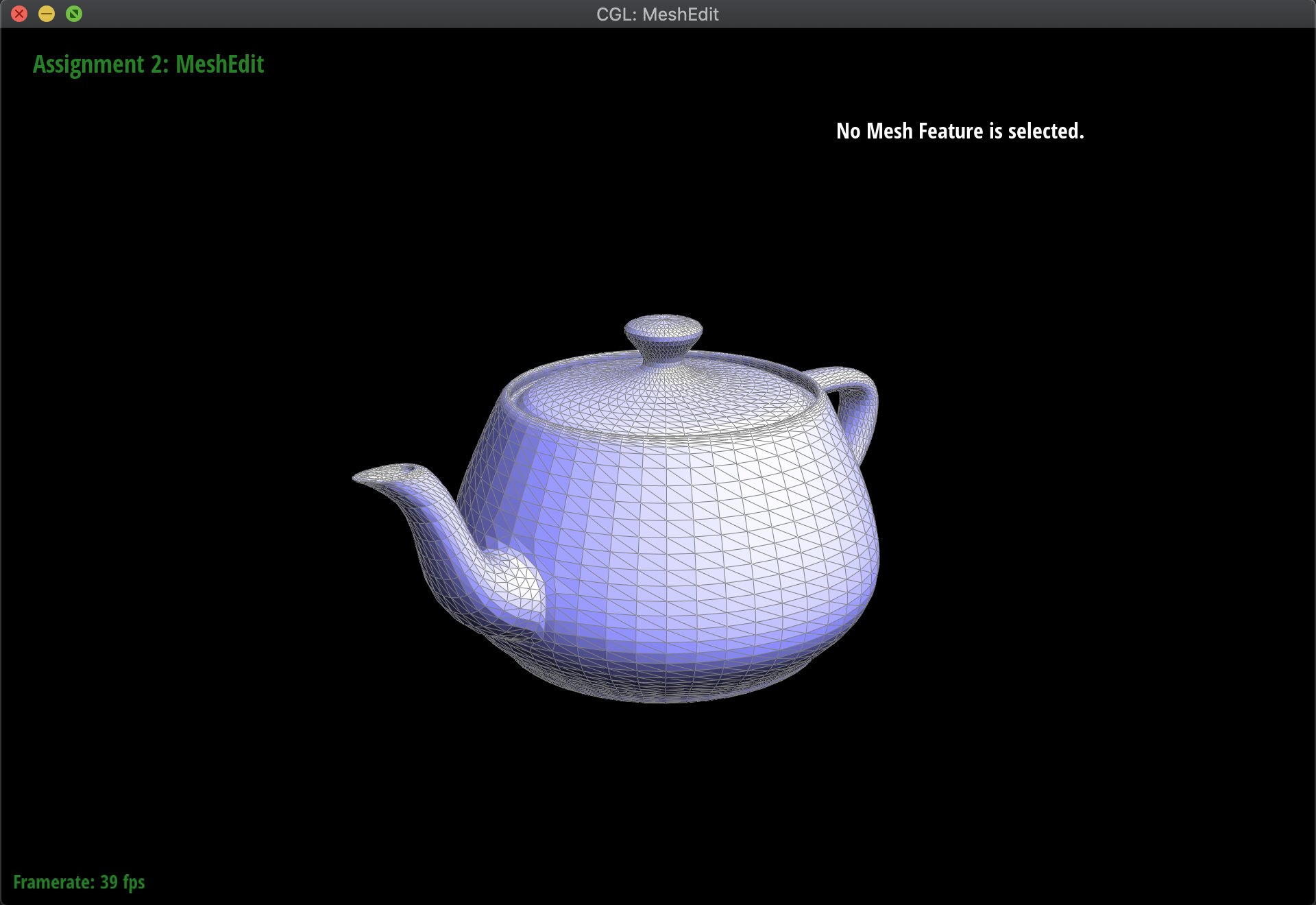
Below are the results of evaluating the Bezier surface in order to form a teapot:
|
|
Section II: Triangle Meshes and Half-Edge Data Structure
Part 3: Average normals for half-edge meshes
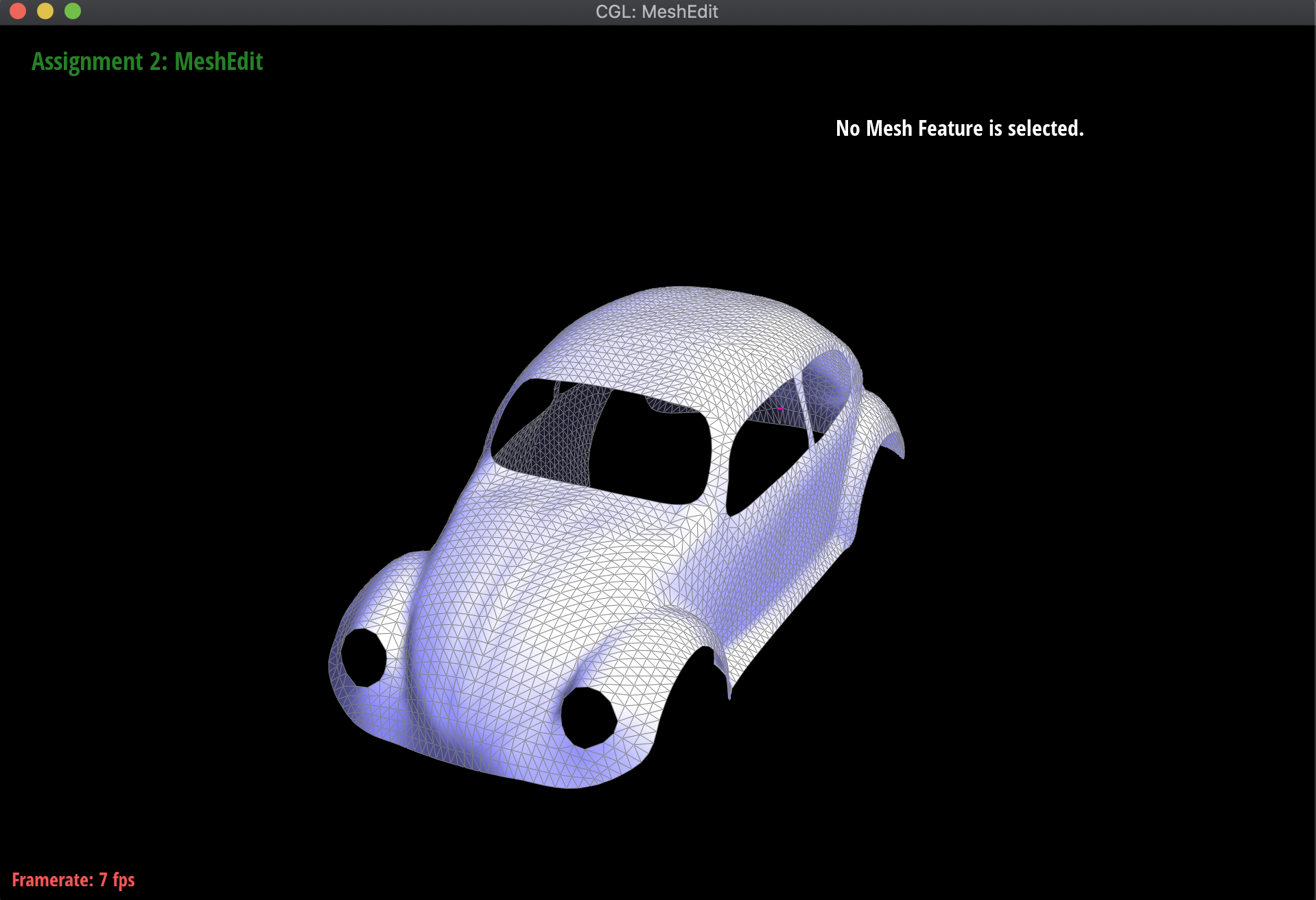
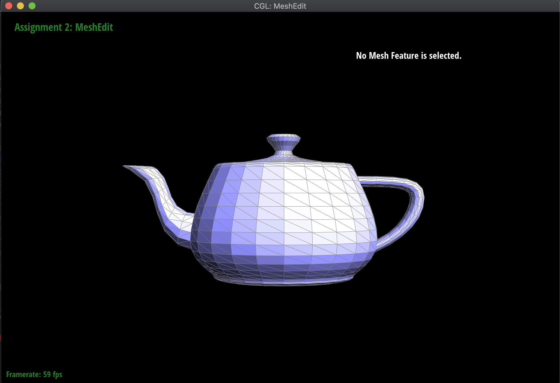
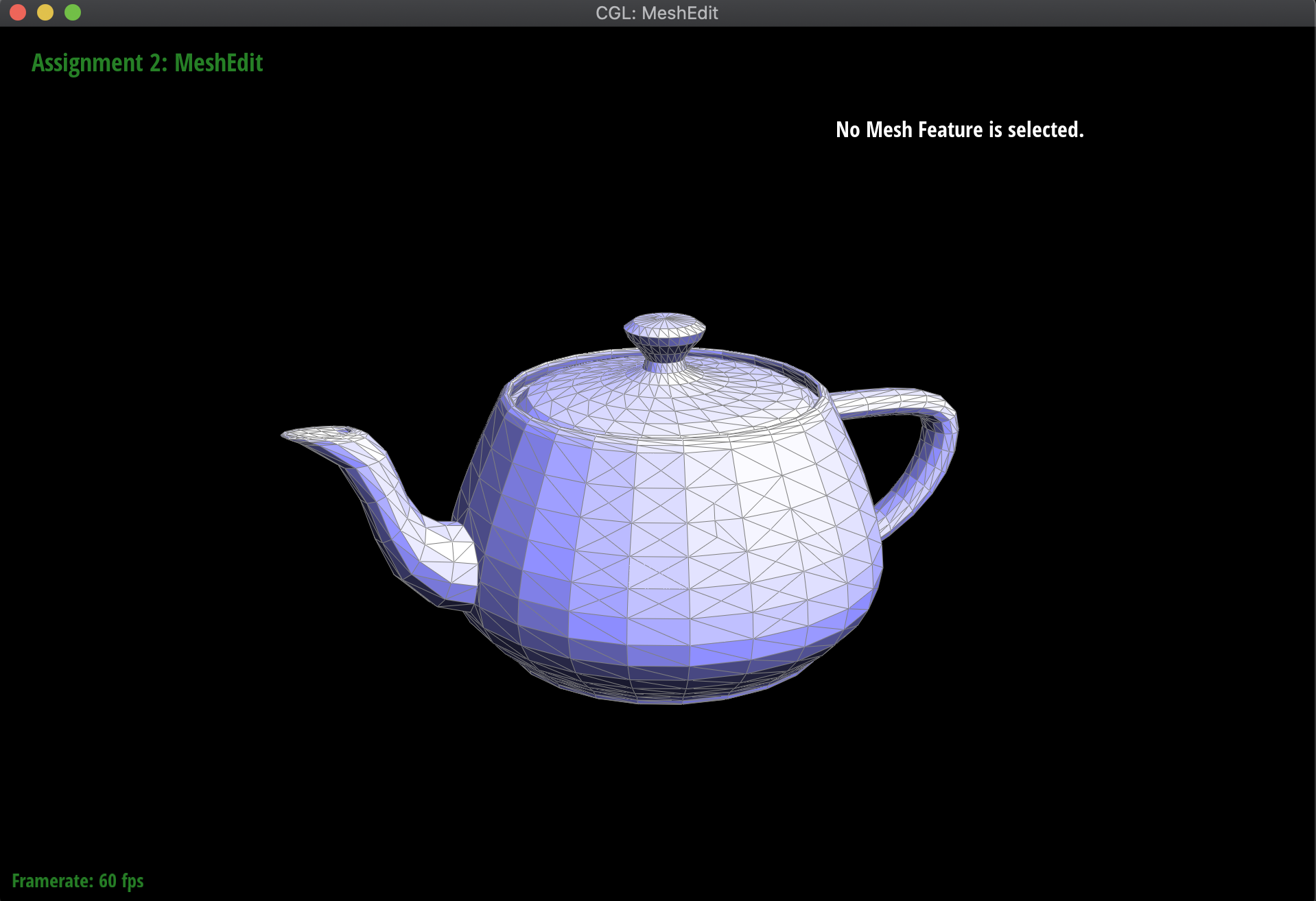
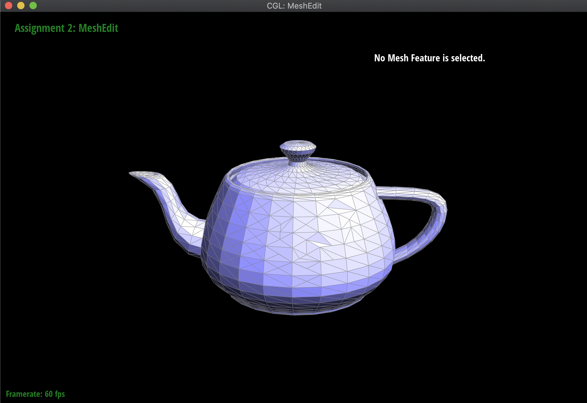
Moving on to meshes and the Half-Edge data structure, I implemented a function normal of a vertex that computed the area-weighted normal vector of the vertex. Essentially, using the Half-Edge data structure to traverse the surrounding triangles around the mesh, I took the normal of the corresponding face, and then scaled it by its area. I computed this area by using the fact that the cross-product divided by two of two vectors is equivalent to the area of the triangle formed by those vectors. Additionally, I needed to check whether the next half-edge that I was computing with was not part of a boundary, in order to handle norm computation for more complex meshes like the Beetle.
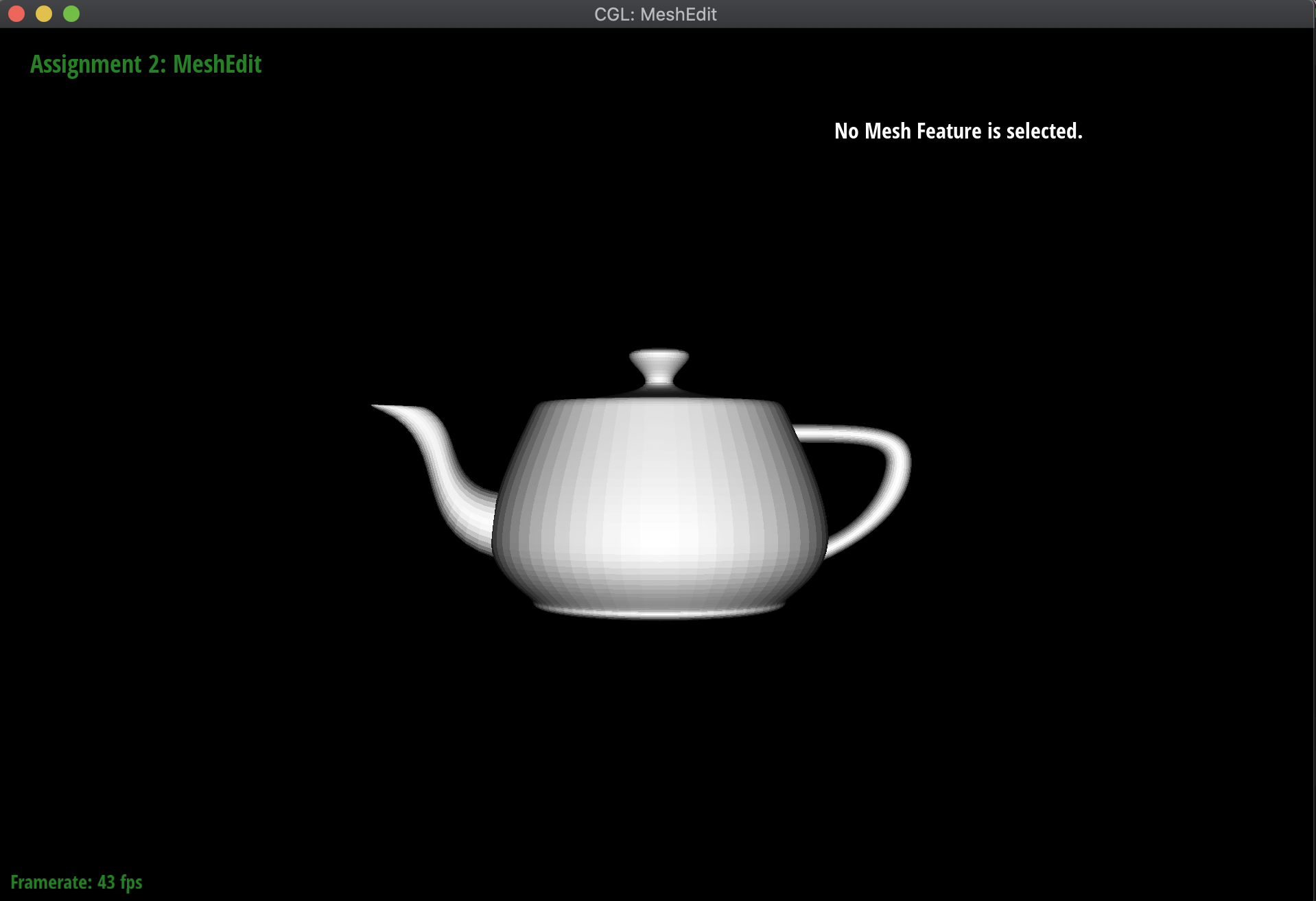
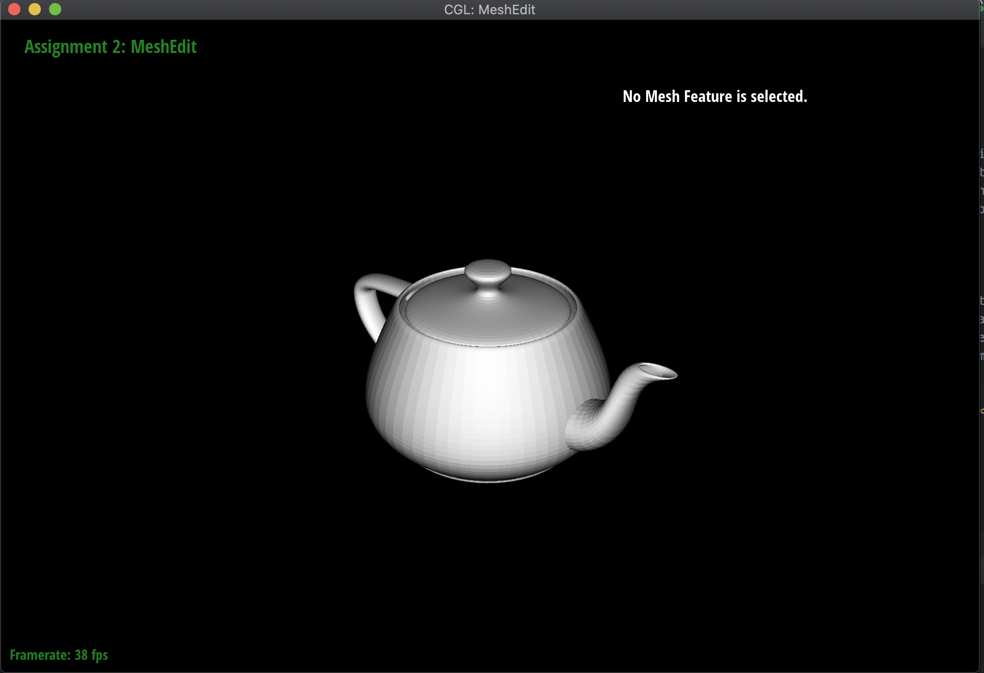
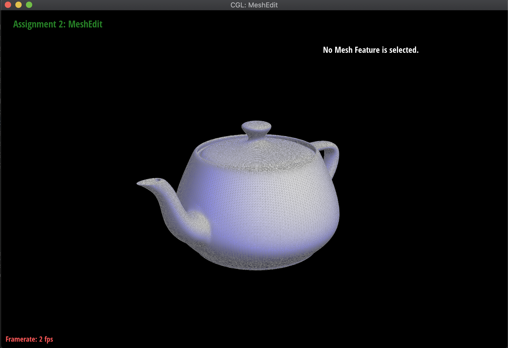
These computed vertex normals can then be used for Phong shading! Below are the meshes of the teapot and the Beetle, both with and without Phong shading activated:
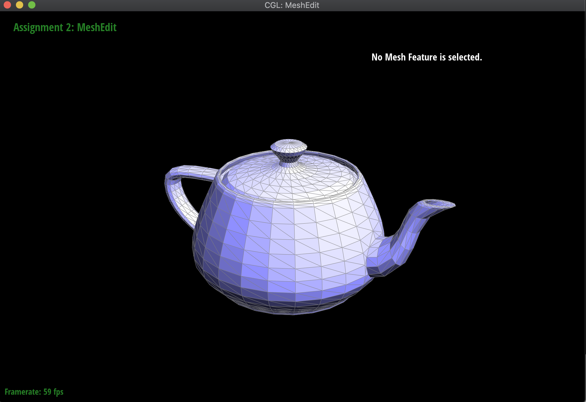
|
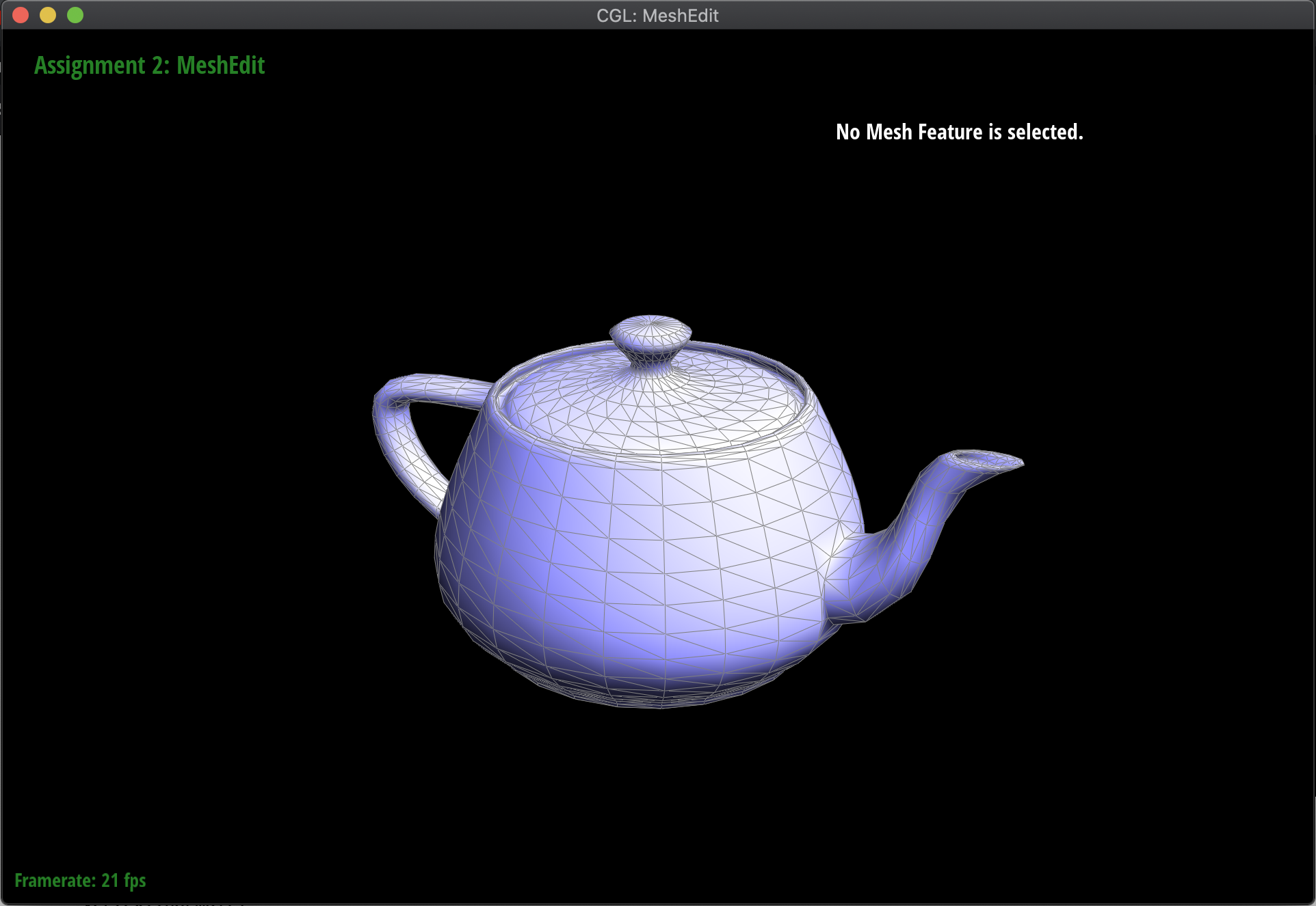
|
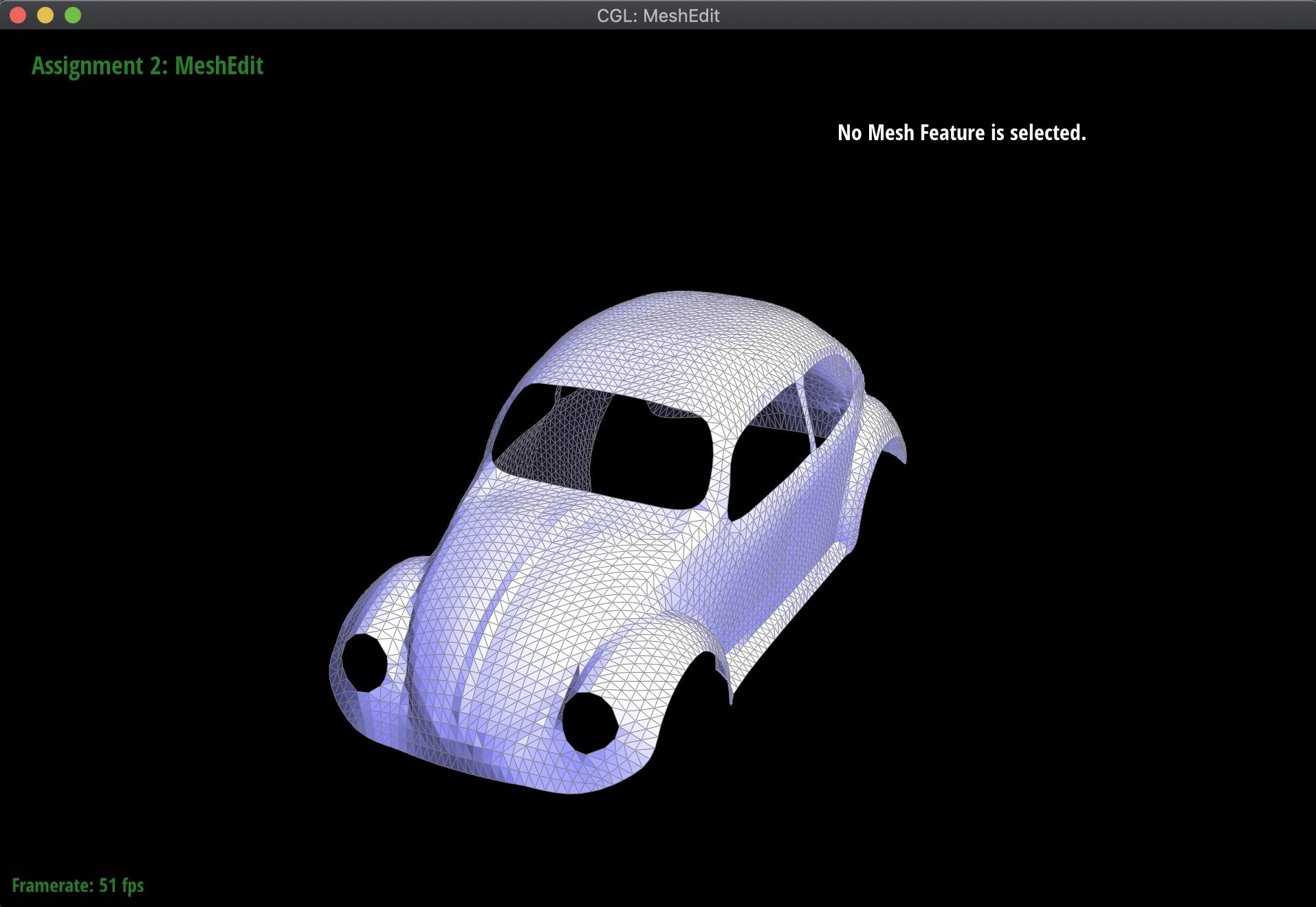
|
|
Part 4: Half-edge flip
The idea behind the edge flip is just to flip the edge between two triangles. For example, if there was a vertical edge along which two triangles are connected to each other, flipping that edge would make it horizontally through the same two triangles. In order to do this, all I needed to do was reassign every pointer that changed between the original position of the edge and the ending position, taking into account every element.
Implementing the edge flip was a very interesting, but tedious process. Originally, I tried to just manually assign everything and jump straight into coding, choosing which pointer should be reassigned while just visually referencing the slides. This was unfeasible, as there was a lot of complexity to keep track of, and essentially what it came down to was me drawing out the diagram of the flip before and after, labelling every half-edge, vertex, face, and edge, and then assigning individually what each would need to point to at the very end of the process. At first, I had some trouble where reassigning the pointers of certain half-edges that were on the border would cause the process to fail and timeout, although I eventually realized that those reassignments were technically unnecessary. Ignoring them completely let the implementation work as intended.
Below are the results of flipping various edges in the teapot mesh:
|

|
Part 5: Half-edge split
Another interesting edge operation to implement was the split, which involved splitting the target edge into two with another edge down the middle. This is very similar in implementation to flip, but also involves creating several new elements in the mesh: 3 new edges, 6 new half-edges, 1 new vertex, and 2 new faces. Basically, I once again drew out the diagram both before and after the split operation, and individually assigned each pointer to its updated reference. Having learned from debugging from the previous part, I was very careful to ensure that the pointers were all matched up correctly, and thus had no bugs implementing the split operation. The only thing I had to be careful of was updating the position of the new vertex m after it was made, but this was just something I forgot upon first writing the code, and was not much of a troubleshooting point.
Below are the results of splitting several edges on the teapot mesh, as well as results of mixing split and flip operations:

|
|
|
For extra credit, I also implemented splitting along the boundary edges, which essentially splits the triangle in half with reference to the boundary edge. To do this, I first checked whether the corresponding edge to split was a boundary edge, and then updated the pointers appropriately. In these cases, there were 2 new edges, 4 new half-edges, 1 new vertex, and 1 new face. Below are the results before and after of splitting some boundary edges on the Beetle mesh:
|
|
Part 6: Loop subdivision for mesh upsampling
Now I used the flip and split operations in order to implement mesh upsampling. To make this work, what I first did was to recalculate the new positions of all the vertices in the mesh, both new and old. Then, I split every edge in the original mesh, and then flipped all the new edges that were created that were connecting a new vertex to an old vertex. Finally, I adjusted every vertex to its new position.
When I first was working on this, I had some issues with the fact that my implementation was flipping edges that were extensions of the original edge that was split, which should have been ignored in the flip; however, when I tried to fix that directly by assigning those isNew values to false, I would get an infinite loop in my split, since I iterated over all 'old' edges. Thus, to fix this problem, I counted the number of edges in the original mesh, and only split edges up to that counter. Then, I was able to set new edges that were actually part of the old edge to false, without having an infinite loop.
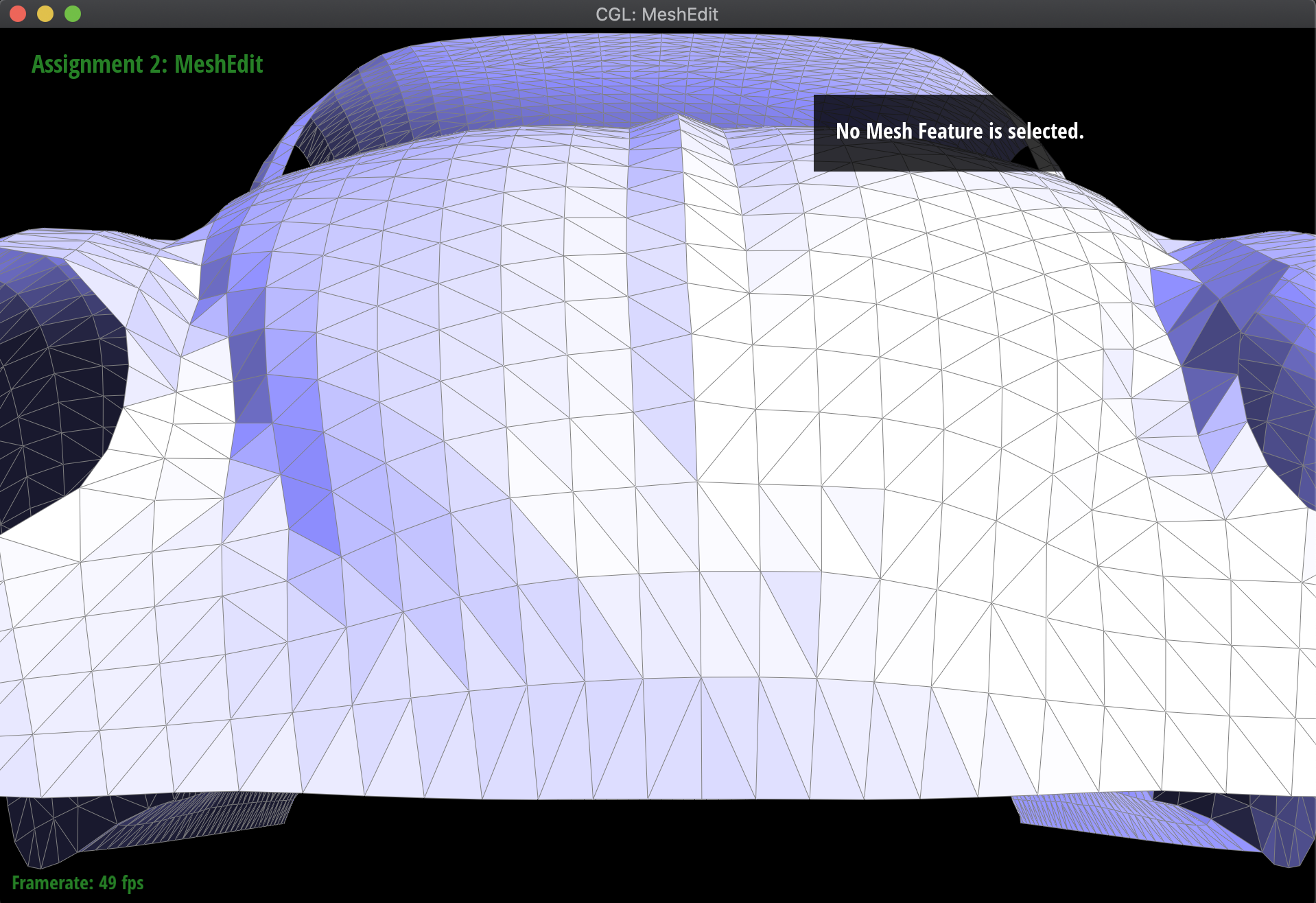
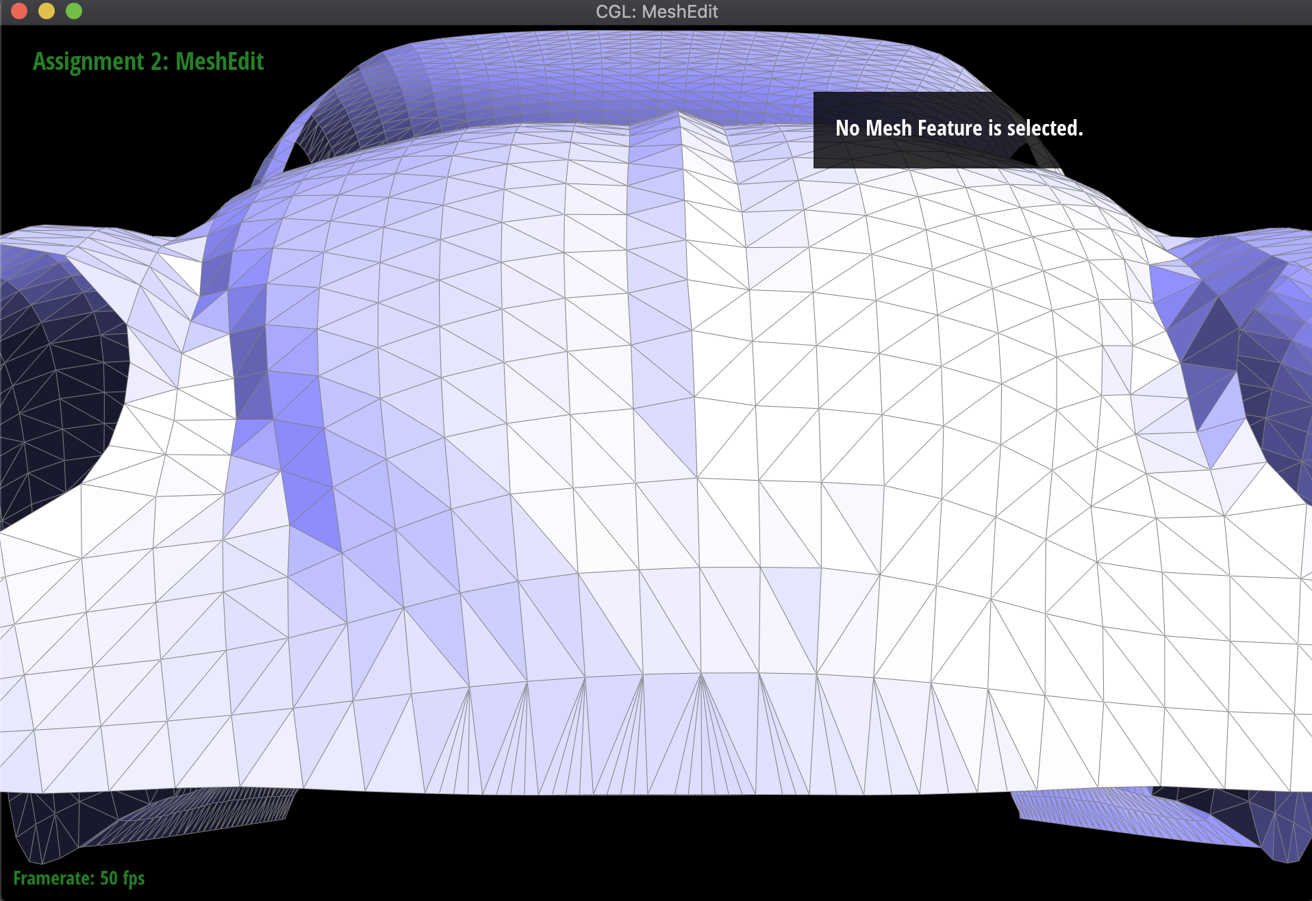
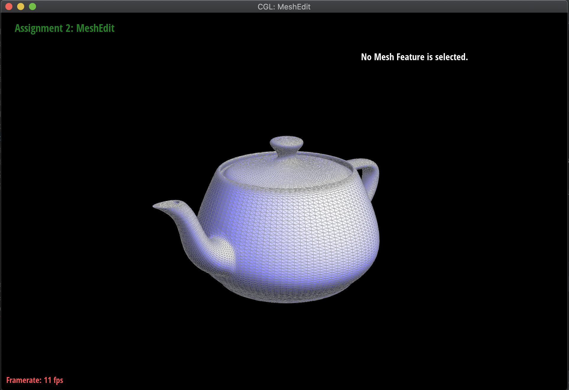
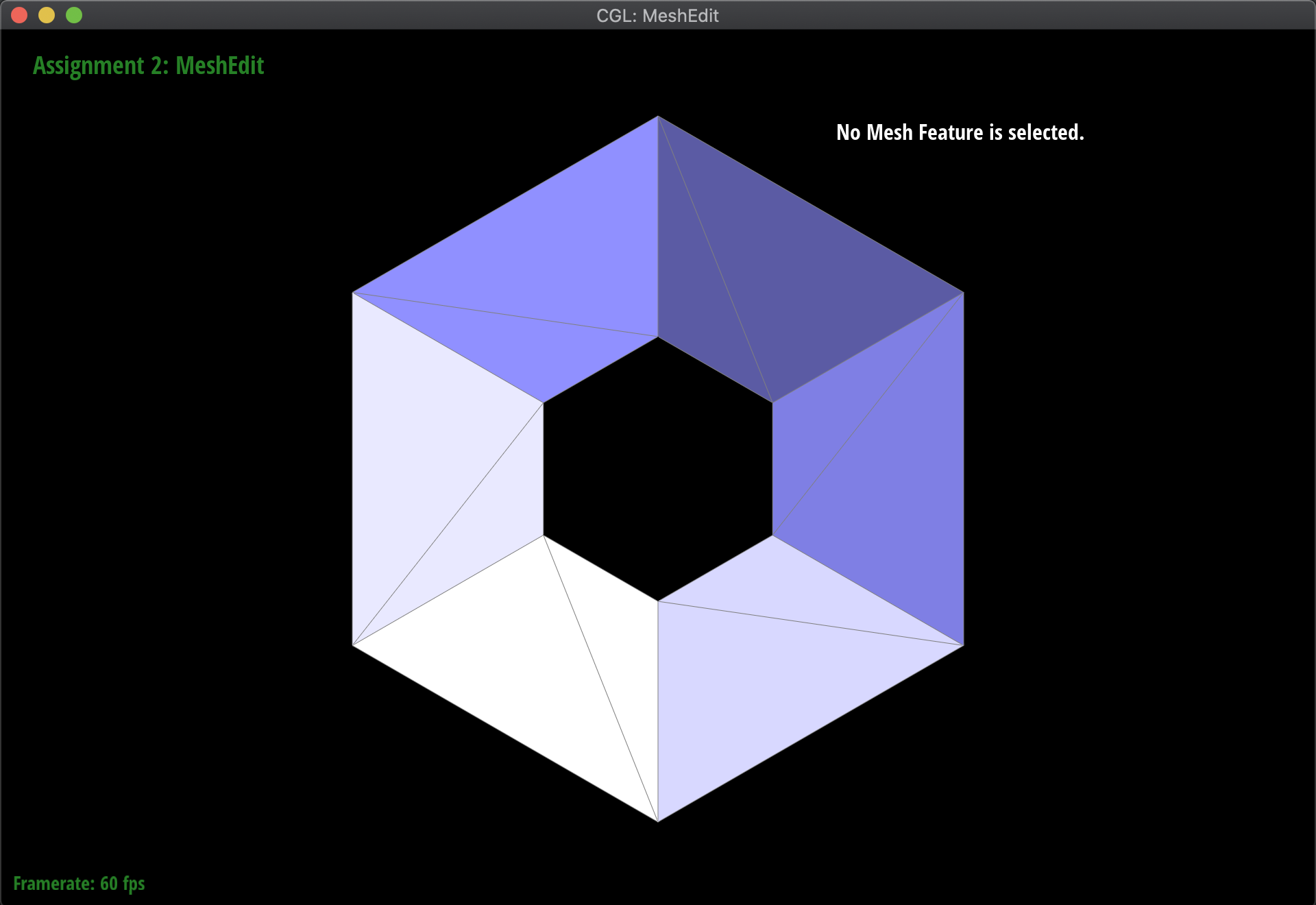
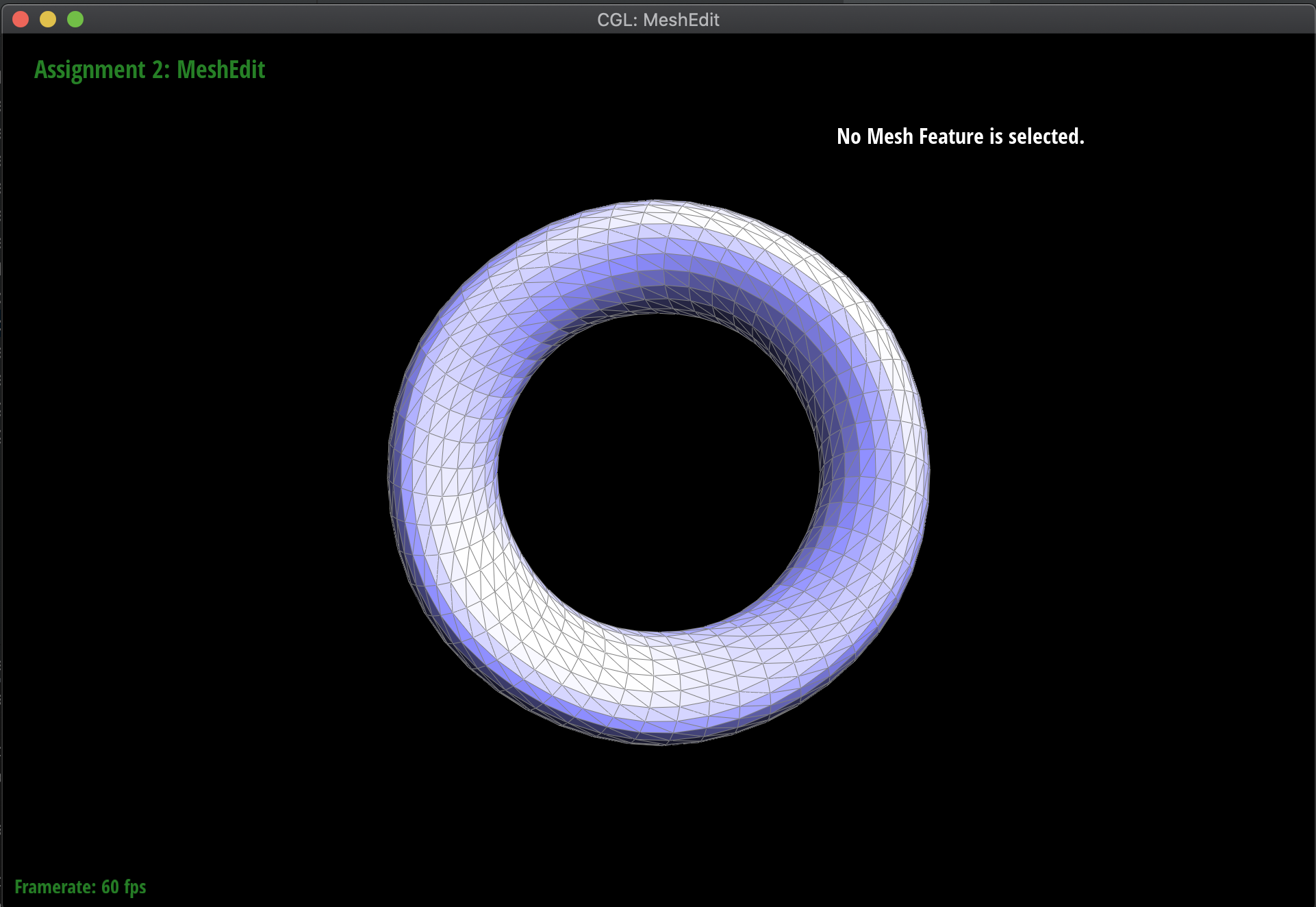
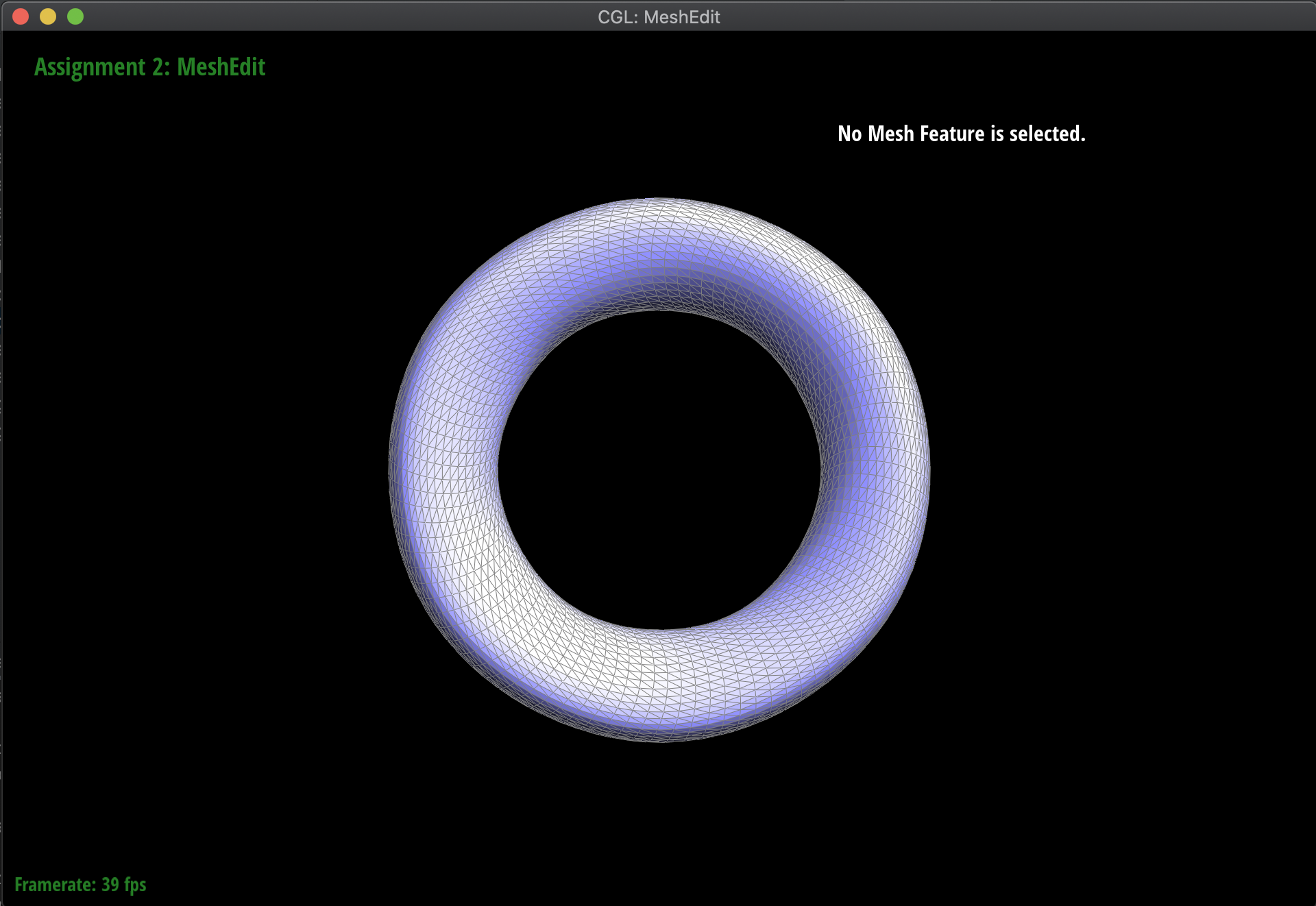
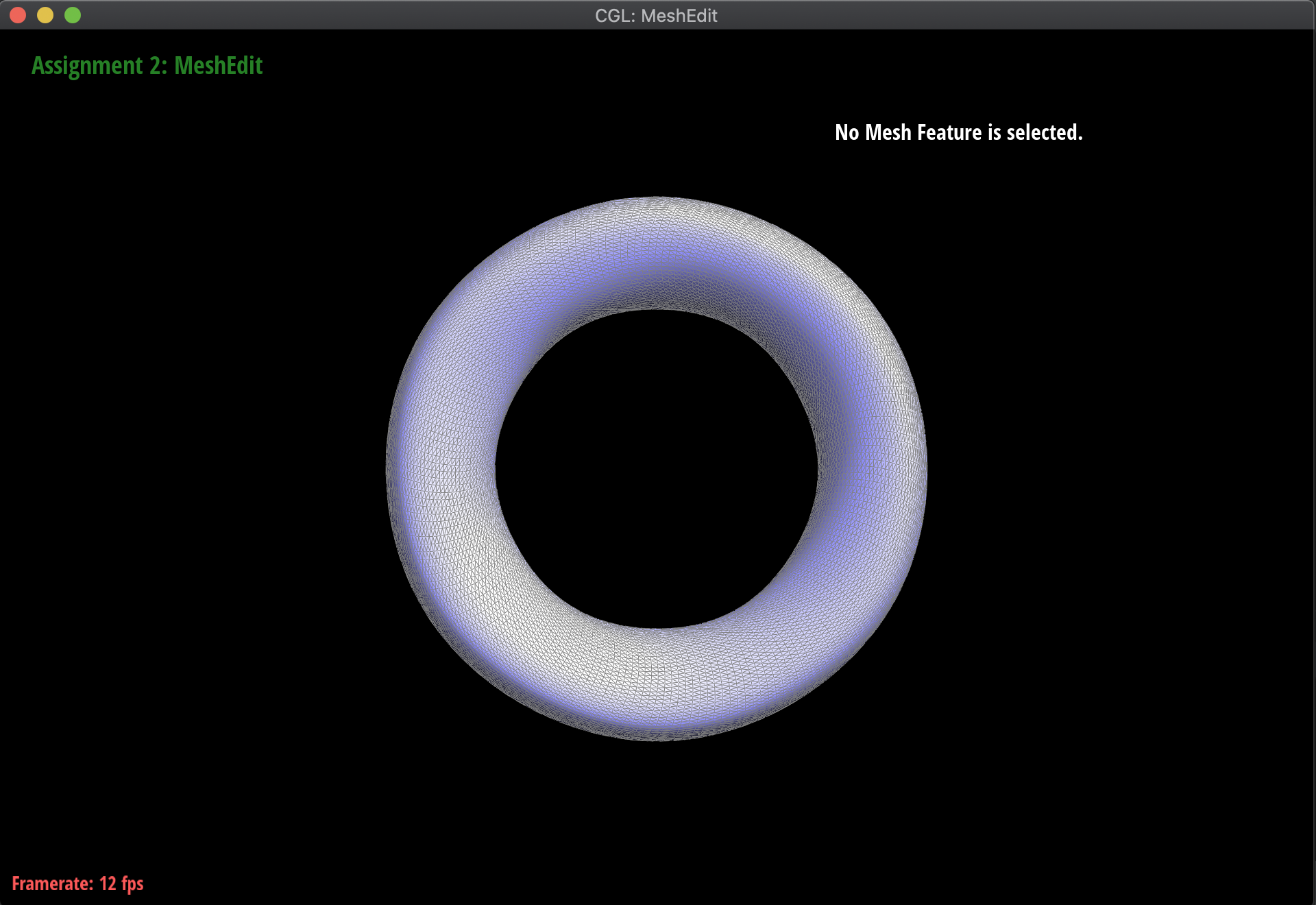
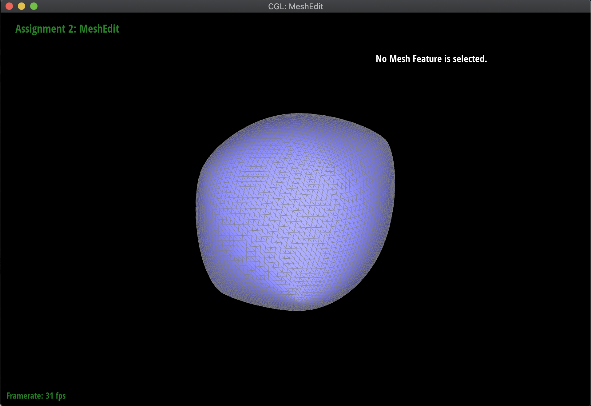
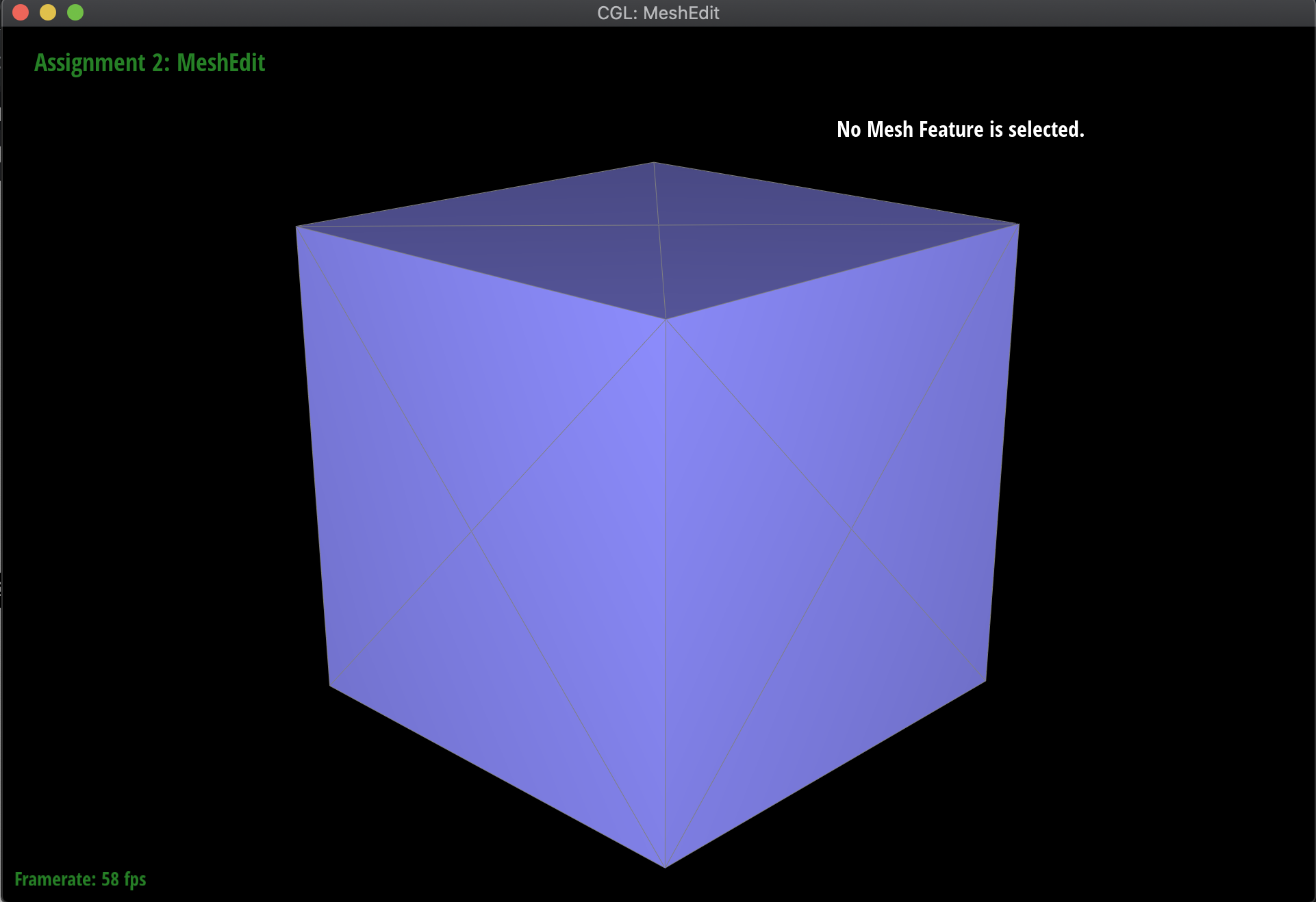
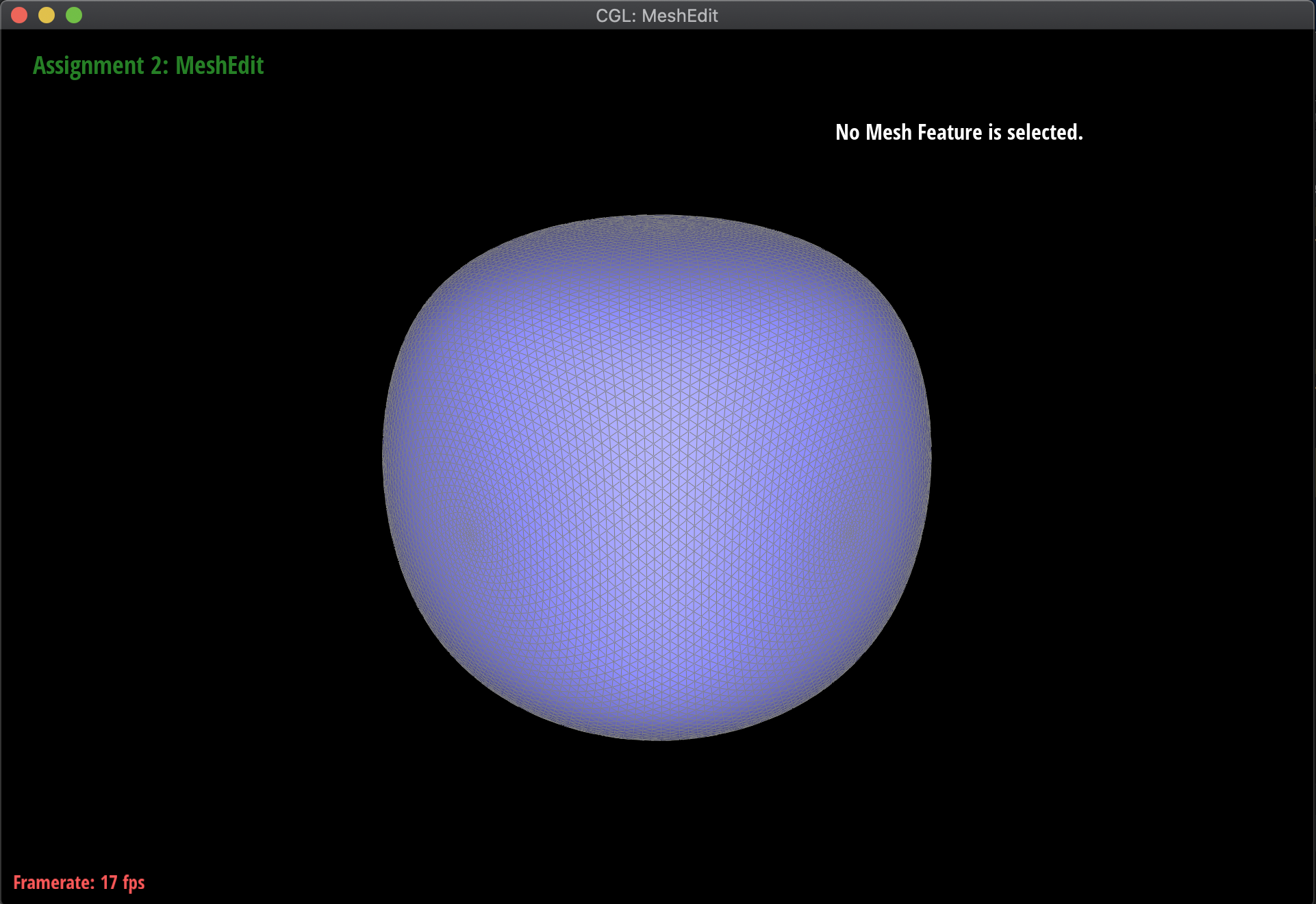
Below are some examples of the subdivision at work, on several meshes. Notice that sharp edges and corners tend to be smoothed out by the process, as we continuously subdivide. Additionally, this is a very computationally heavy operation, in the sense that as we subdivide lower and lower, the mesh has exponentially more triangles to work with:

|
|
|
|
|
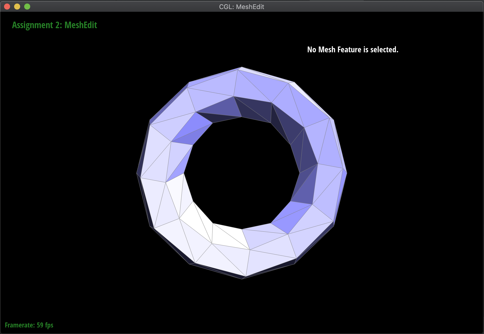
|
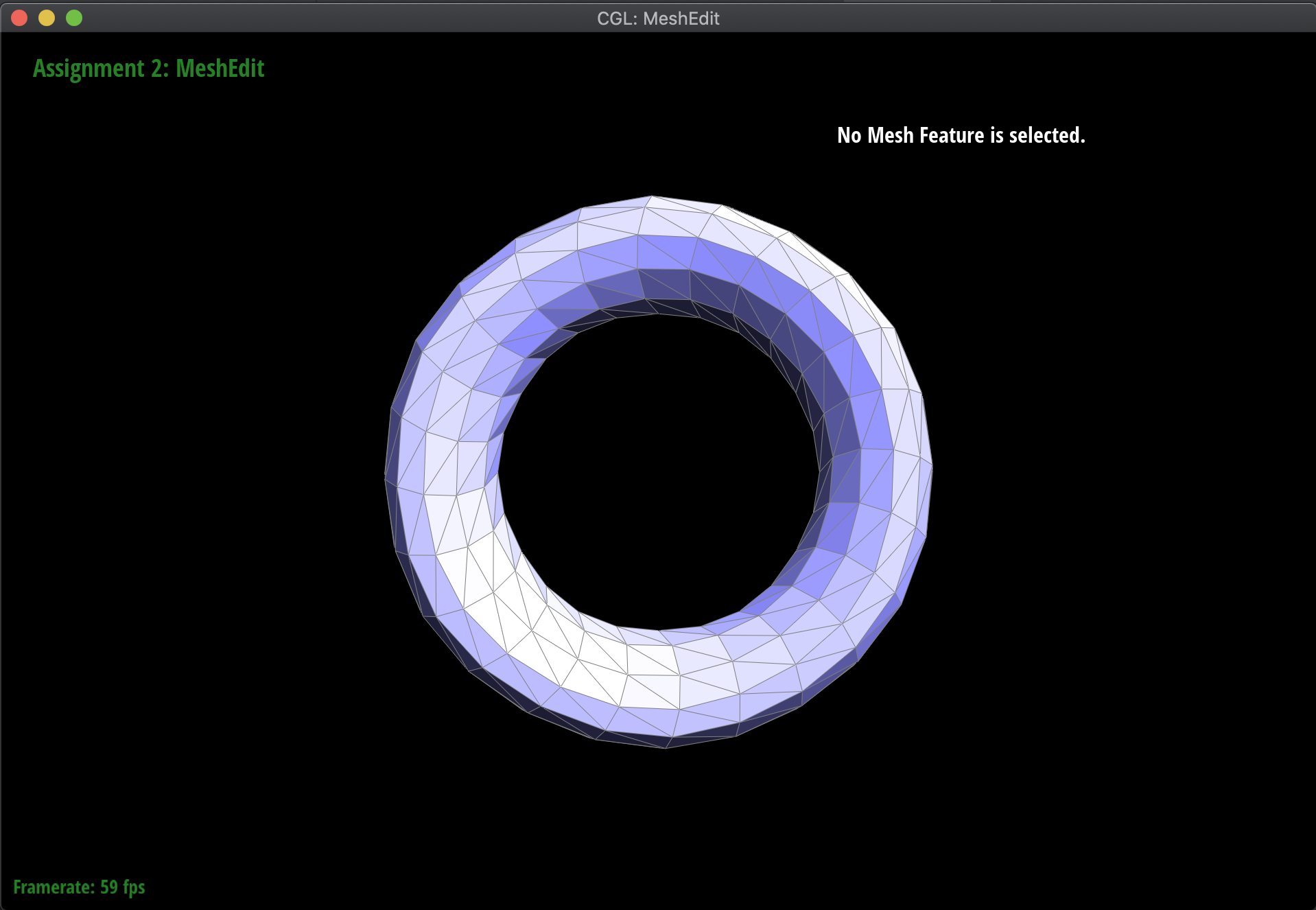
|
|
|
|
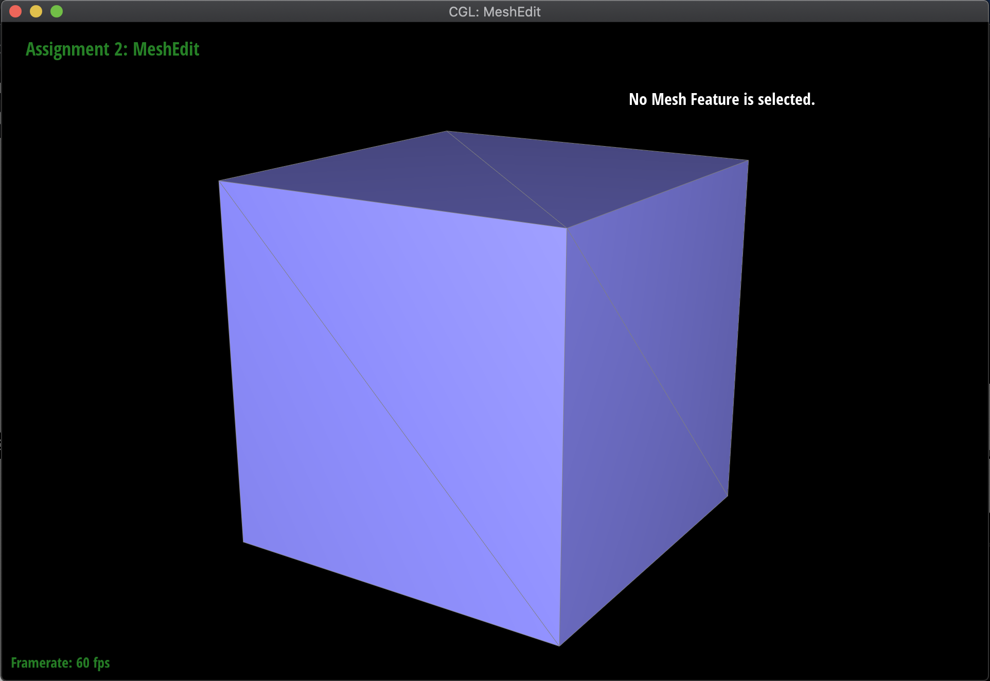
After subdividing the cube mesh below, without any pre-processing, the result is an asymmetric, lopsided blob. This is because the original mesh was asymmetric, as a result of sharp corners and edges. In order to fix this, I split various edges in the cube such that the original mesh was symmetric, resulting in a uniform subdivision. The resulting before and afters of the cube are below. The difference between the pre-processed and original meshes before subdivision are just that the pre-processed one has faces split into four uniform triangles, that are symmetric all around, whereas the original is just two triangles that are not symmetric:
|
|
|
|
Section III: Mesh Competition
Didn't do it :(